
Foreword
Safety instructions
Revision history
Privacy Notice
About this guide
Precautions and warnings
Operational requirements
Installation requirements
Introduction
Overview
Technical Specifications
Package contents
Design
Description
Dimensions
Adding to the system
Installation
Detection Parameters
Battery replacement
Configuration
Status display
Detector configuration
Wired input configuration
Sensor
Sabotage
Key zone
Warranty
Network intelligent fire camera compatible with the ProSAFE and FireSAFE applications
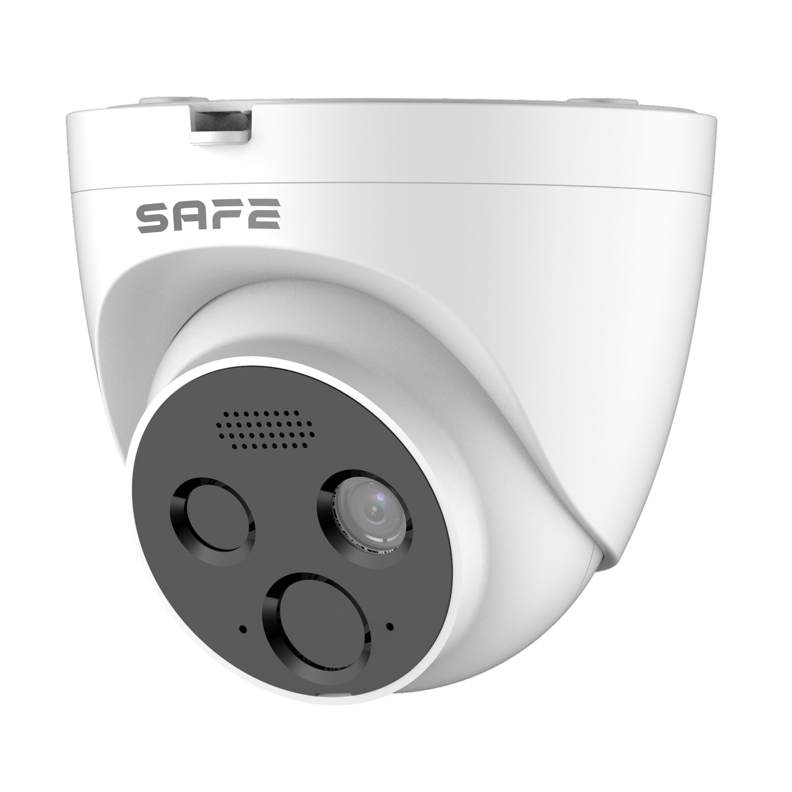
SAFE Turret Cam AI (SAFE 64220)
Foreword
General
This manual introduces the functions, installation and operation of the camera.
Safety instructions
The following symbols with defined meanings may appear in this manual.
| Symbols | Meaning |
|---|---|
| ⚠ WARNING | Indicates a medium or low potential hazard which could cause minor or moderate injury if not avoided. |
| ⚠ CAUTION | Indicates a potential risk which could result in property damage, data loss, reduced performance or an unpredictable result. |
| ⚠ NOTE | It provides additional information, such as highlighting and adding to the text. |
About this guide
- This manual serves only as a reference guide. In case of a discrepancy between the manual and the actual product, the actual product prevails.
- We are not liable for any losses caused by use that is not in accordance with the manual.
- The manual will be updated in accordance with the latest laws and regulations of the related regions. For detailed information, see the paper manual, the CD-ROM, the QR code or our official website. In case of a discrepancy between the paper and the electronic version of the manual, the electronic version prevails.
- All designs and software are subject to change without prior written notice. Product updates may cause certain differences between the actual product and the manual. Contact customer service for the latest program and supplementary documentation.
- Nevertheless, there may be deviations in technical data, descriptions of functions and operations, or printing errors. In case of any doubt or dispute, please refer to our final explanation.
- If the manual (in PDF format) cannot be opened, update your reader software or try another common reader software.
- All trademarks, registered trademarks and company names mentioned in the manual are the property of their respective owners. If any problem occurs while using the device, visit our website,
contact your supplier or customer service. - In case of any doubt or dispute, please refer to our final statement.
Important safety precautions and warnings
Electrical safety
- All installation and operation should comply with local electrical safety regulations.
- The power supply must comply with the requirements of the SELV (Safety Extra Low Voltage) standard and supply the device with a rated voltage that meets the power source requirements of IEC60950-1. Please note that the power supply requirement is governed by the device label.
- Before starting the device, make sure that the power supply is correct.
- An easily accessible disconnect device must be incorporated into the building's installation wiring.
- Prevent damage to the power cable, especially the plug, socket and the joints leading from the device.
- Do not aim strong light at the device, such as lamp light or sunlight; otherwise excessive brightness or light trails could occur, which are not a device malfunction, and they affect the service life of the CMOS (Complementary Metal-Oxide Semiconductor) semiconductors.
- Do not place the device in a damp or dusty environment, at extremely high or low temperatures, in places with strong electromagnetic radiation or unstable lighting.
- To prevent damage to the internal components, keep the device away from liquids. Keep indoor devices away from rain or moisture to prevent fire or lightning strike.
- Ensure good ventilation to prevent heat accumulation.
- Transport, use and store the device within the permitted humidity and temperature ranges.
- Strong stress, violent vibration or splashing water are not permitted during transport, storage and installation.
- When transporting the device, pack it in the standard factory packaging or equivalent material.
- Install the device in a location accessible only to professional personnel with appropriate knowledge of safety protections and warnings. Non-professionals entering the installation area while the device is in normal operation could suffer accidental injury.
- Do not touch the heat dissipation component of the device to avoid burns.
- When disassembling the device, carefully follow the instructions in the manual; otherwise water leakage or degraded image quality could occur due to improper disassembly. Before installing the cover, make sure the sealing ring is flat and correctly installed in the groove. If condensed mist appears on the lens after unpacking, or if the desiccant turns green, contact after-sales service to have the desiccant replaced. (Not all models are supplied with desiccant.)
- It is recommended to use the device together with lightning protection.
- To increase reliability, it is recommended to ground the device.
- Do not touch the image sensor (CMOS) directly. Dust and dirt can be removed with a blower, or you can gently wipe the lens with a soft cloth moistened with alcohol.
- The device body can be cleaned with a soft dry cloth, which, when moistened with a mild detergent, can also be used to remove stubborn stains. To prevent possible damage to the device body coating, which could cause reduced performance, do not use volatile solvents such as alcohol, benzene, thinner, etc., or strong, abrasive cleaning agents to clean the device body.
- The dome cover is an optical component; during installation or operation do not touch the cover or wipe it directly with your hands. To remove dust, grease or fingerprints, gently wipe with oil-free cotton moistened with diethyl ether or with a moistened soft cloth. You can also use an air blower to remove dust.
⚠ WARNING
- Strengthen the protection of the network, device data and personal data by adopting measures that include, but are not limited to, using a strong password, changing the password regularly, updating the firmware to the latest version and isolating the computer network. On some devices with old firmware versions, the ONVIF password does not change automatically together with the change of the system password, and the firmware must be updated or the ONVIF password updated manually.
- Use the standard components or accessories supplied by the manufacturer and make sure the device is installed and maintained by professional technicians.
- The surface of the image sensor should not be exposed to laser beam radiation in an environment where laser beam devices are used.
- Unless stated otherwise, do not provide two or more power sources for the device.
Failure to follow this instruction may cause damage to the device.
Introduction
Seal all cable joints watertight with insulating tape and waterproof tape to prevent short circuit and water damage. For detailed operating information, see the FAQ manual.

| No. | Port name | Description |
|---|---|---|
| 1 | Power input | Inputs for 12 VDC power supply. Make sure that the power supply is provided according to the instructions in the manual. ⚠ An incorrect power supply may damage the device. |
| 2 | LAN | Connects to the network using a network cable. Powers the device via PoE. 📖 PoE is available on selected models. |
| 3 | Alarm inputs / outputs | Includes alarm signal input and output ports, whereby the number of I/O ports may differ between devices. For detailed information, see the Alarm information table |
| Port | Port name | Description |
|---|---|---|
| Alarm inputs and outputs | ALARM_OUT | Sends an alarm signal to the alarm device. When connecting to the alarm device, it is necessary to enter only the ALARM_OUT port, and the ALARM_OUT_GND port with the same number can be used together. |
| ALARM_OUT_GND | ||
| ALARM_IN | Receives the switching signal of an external alarm source. Connect different alarm input devices to the same ALARM_IN_GND port. | |
| ALARM_IN_GND |
Alarm input/output connection
The camera can be connected to an external alarm input / output device via the digital input/output.
📖 The alarm input/output is available on selected models.
Step 1. Connect the alarm input device to the alarm input end of the I/O port. The device collects different states of the alarm input port when the input signal is idle and grounded.
- The device reads logical "1" when the input signal is connected to +3 V to +5 V or is idle.
- The device reads logical "0" when the input signal is grounded.

Step 2. Connect the alarm output device to the alarm output end of the I/O port. Alarm output
- Mode A: Level application. The alarm outputs have high and low levels, and the alarm output is OD, which requires an external pull-up resistor (typically 10 K Ohm) to function. The maximum external pull-up level is 12 V, the maximum port current is 300 mA, and the default output signal is high level (external pull-up voltage). The default output signal switches to low level when there is an alarm on the output (As long as the operating current is lower than 300 mA, the output low-level voltage is lower than 0.8 V).
- Mode B: Switch application. The alarm output is used to control an external circuit; the maximum voltage is 12 V and the maximum current 300 mA. If the voltage is higher than 12 V, use an additional electrical relay.

Step 3. Log in to the web interface and configure the alarm input and alarm output in the alarm settings.
- The alarm input in the web interface corresponds to the alarm input end on the I/O port. When an alarm occurs, the alarm input device will generate a high-level and low-level alarm signal; set the input mode to "NO" (default) if the alarm input signal is logical "0", and to "NC" if the alarm input signal is logical "1".
- The alarm output in the web interface corresponds to the alarm output end of the device, which is also the alarm output end of the I/O port.
Network configuration
Device initialization and IP setting can be completed using the ConfigTool or in the web interface. For more information, see the web interface operation manual.
- Device initialization is available on selected models and is required on first use and after resetting the device.
- Device initialization is available only if the IP addresses of the device (192.168.1.108 by default) and the computer remain in the same network segment.
- Properly plan the applicable network segment for connecting the device to the network. The following figures and interfaces are for reference only, and the actual product prevails.
Device initialization
Step 1. Double-click "ConfigTool.exe" to open the tool.
Step 2. Click Modify IP. The Modify IP interface window is displayed.
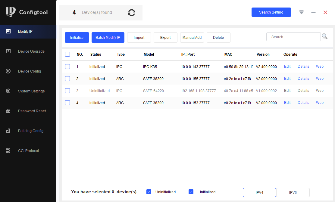
Step 3. Click the option Search setting. The interface is displayed Setting.
Step 4. Enter the start IP address and end IP address of the network segment in which you want to search for devices, and click OK.
A list of all devices found in the network segment is displayed.
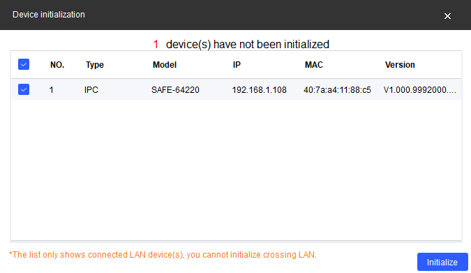
Step 5. Select one or more devices whose status is uninitialized, and click Initialize. If you cannot see the device, try pausing the firewall for 10 min. The device initialization.
Step 6. Select the devices that need to be initialized and click Initialize. The password setting interface is displayed.
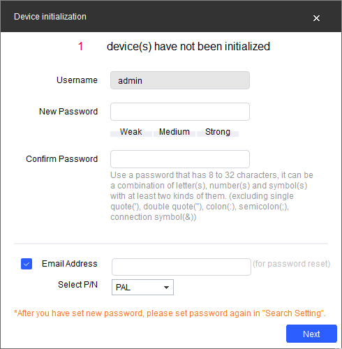
Step 7. Set and confirm the device password, then enter a valid e-mail address. Click Next. The final setting interface is displayed. The password can be changed or reset in System settings.
Step 8. Select the options according to your needs and click OK. When the initialization is complete, the Initialization.
Click the success icon (✅) or the failure icon ( ) to display the details.
Step 9. Click Finish. The device status in the Modify IP changes to Initialized.
Modifying the device IP address

- You can modify the IP address of one or more devices at once. This section is based on batch modification of IP addresses.
- Batch modification of IP addresses is available only if the relevant devices have the same login password.
Step 1. Perform steps 1 to 4 in section "2.1 Device initialization" and search for the device in the network segment.
After clicking Search setting enter user name a password, make sure they are the same as those you set during initialization, otherwise the message "wrong password" will be displayed.
Step 2. Select the devices whose IP addresses need to be modified, and click Modify IP. The interface is displayed Modify IP Address.
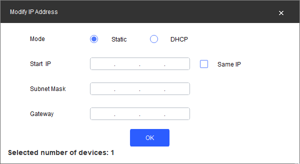
Step 3. Select Static mode and enter the start IP address, subnet mask and gateway.
- If you select Same IP, the IP addresses of multiple devices will be set to the same value.
- If a DHCP server is available on the network, the devices will automatically obtain IP addresses from the DHCP server after selecting DHCP.
Step 4. Click OK. In case of an error, check whether the camera access passwords (entered during initialization) and those in the "Search Settings" menu are the same.
Logging in to the web interface
Step 1. Open a browser, enter the device IP address in the address bar and press Enter.
If the setup wizard appears, complete the setup according to the instructions.
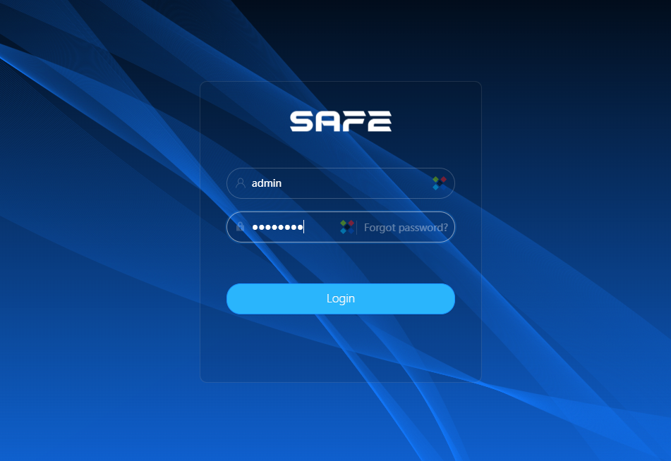
Step 2. Enter the username and password in the login box and click Login.
Step 3. For the first login, click the button: „Click here to download the plugin“ and install the plugin according to the instructions. After the installation is complete, the main interface is displayed.

Installation
Packing list
The tool required for installation, such as an electric drill, is not included in the package.

Dimensions

Adding the camera to the system
In each application, the camera behaves as a separate device, where each image (visible/thermal) is a separate video channel. The camera therefore occupies 2 positions on the NVR.
FireSAFE
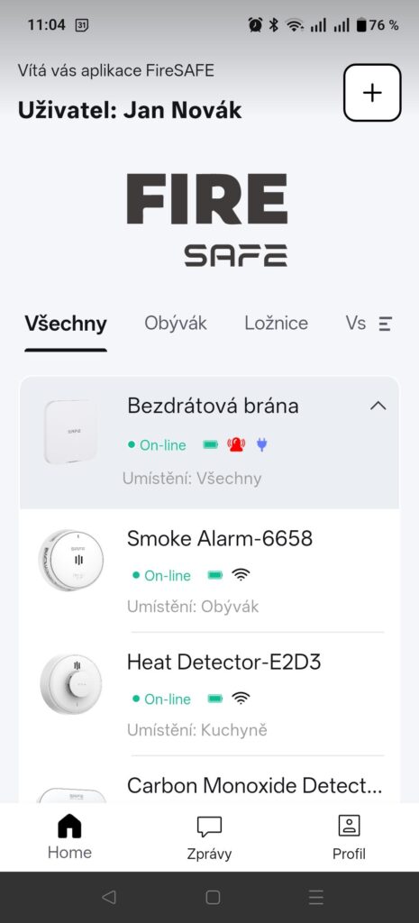
The FireSAFE application is a specialized fire safety application with sensors and the control panel of the FireSAFE system, such as the 10Y30 – RF smoke detector or the 10YDCO – RF carbon monoxide (CO) detector.
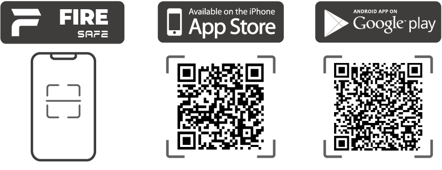
Step 1. Download and install the FireSAFE application from Google Play or the App Store. (https://www.smart-safe.eu/firesafe/app/)
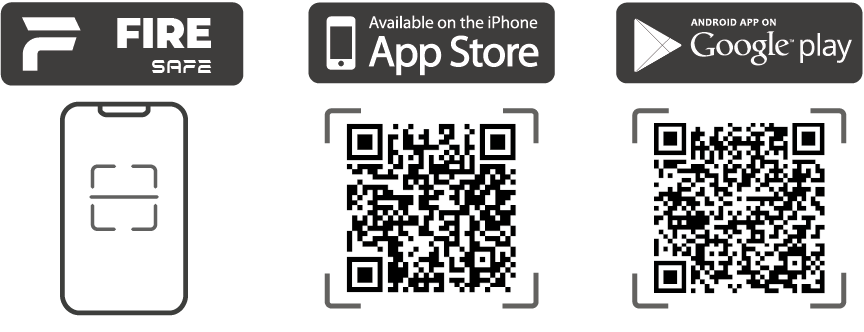
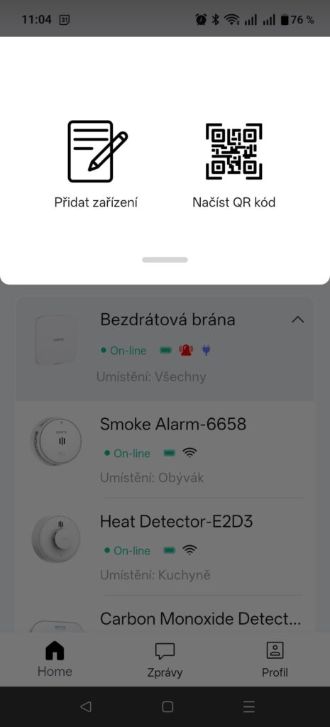
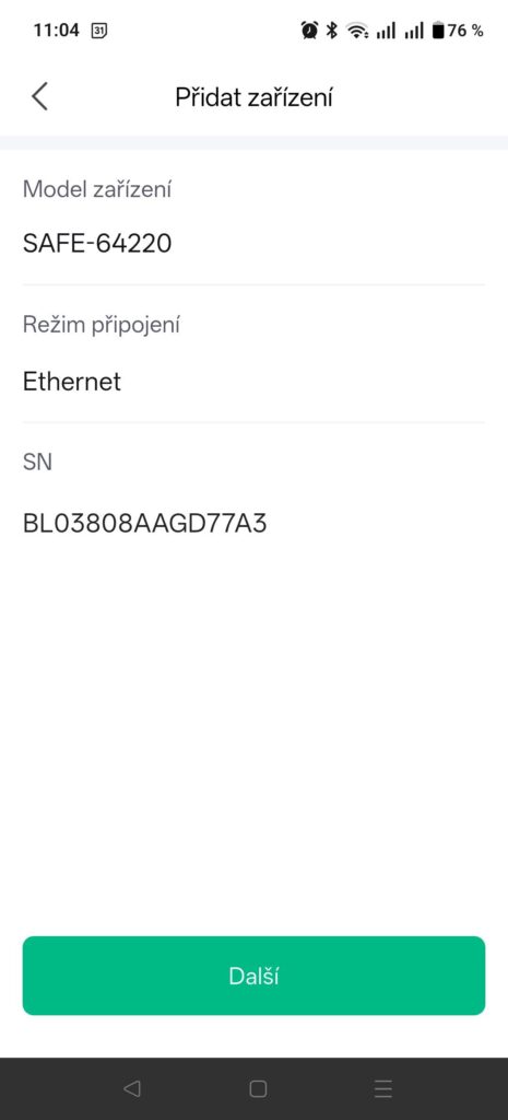
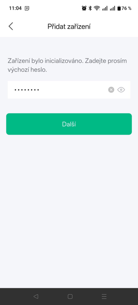
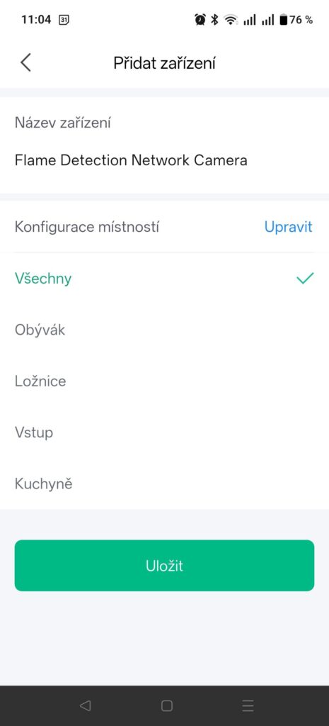
Step 2. After launching the application, registering and creating an account according to the application instructions, add the camera by clicking the + button, scan the QR code of the device and enter the password as during initialization. This adds the camera to the system as a visual flame or temperature detector.
Step 3. In the camera web interface at its IP address you can set detection limits, detection types (temperature, flame, motion) and detection zones. All in the "Event", or "Event„.
ProSAFE
In each application, the camera behaves as a separate device, where each image (visible/thermal) is a separate video channel. The camera therefore occupies 2 positions on the NVR.
Step 1. Download and install the ProSAFE application from Google Play or the App Store. (https://www.smart-safe.eu/prosafe/app/)
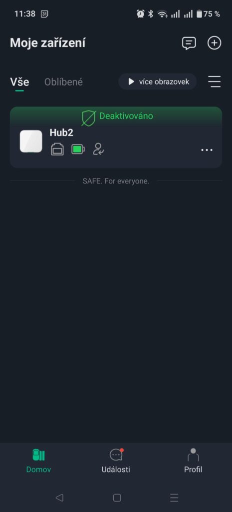
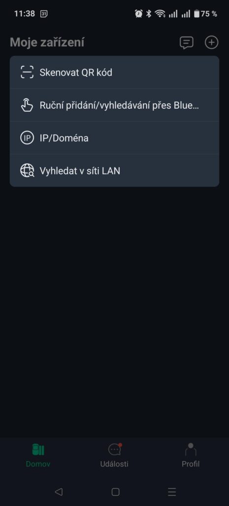
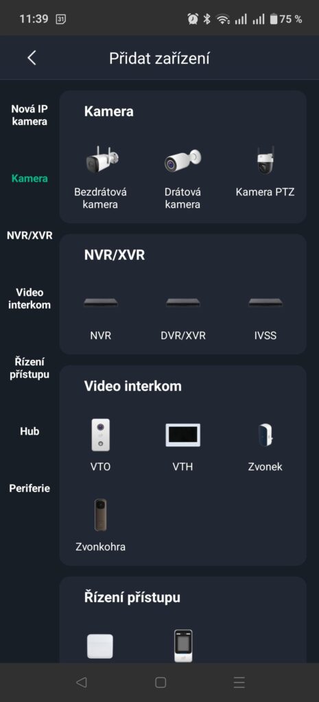
Step 2. After launching the application, registering and creating an account according to the application instructions, add the camera by clicking the button + , select the option "Scan QR code", scan the device QR code. Select "Camera„, „Wired camera". Enter the camera name and the same password as during camera initialization. Select whether you want to use daylight saving time and UPnP mode.
Step 3. In the camera web interface at its IP address you can set detection limits, detection types (temperature, flame, motion) and detection zones. All in the "Event" menu, or "Event„.
Step 4. After adding the camera you can enable RTSP encryption via TLS, thus securing the image transmission as follows: In the ProSAFE app, click on the camera image, then on "wheel" settings in the upper right, then the "More" menu and here switch the RTSP over TLS button.
With this procedure, you have added the camera as a display device that autonomously and locally detects the required event without notification in the ProSAFE application. However, it is not connected to the ProSAFE alarm system and works independently. If you want to use the camera only as a fire protection system, use the FireSAFE application directly.
ProSAFE in conjunction with the SAFE HUB 2 Plus control panel
In each application, the camera behaves as a separate device, where each image (visible/thermal) is a separate video channel. The camera therefore occupies 2 positions on the NVR.
Step 1. Download and install the ProSAFE application from Google Play or the App Store. (https://www.smart-safe.eu/prosafe/app/)
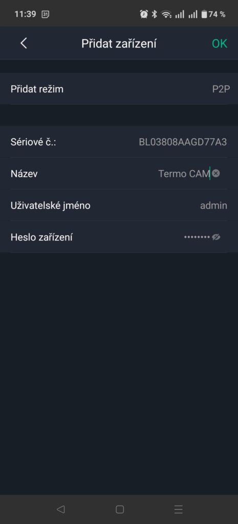
Step 2. Add the IP camera as a "sensor" to the selected HUB 2 Plus by clicking HUB – Devices – the + button in the upper right – Add IP camera – fill in, or + in the upper right – find on the LAN. For fire detection select channel 2 (thermal).
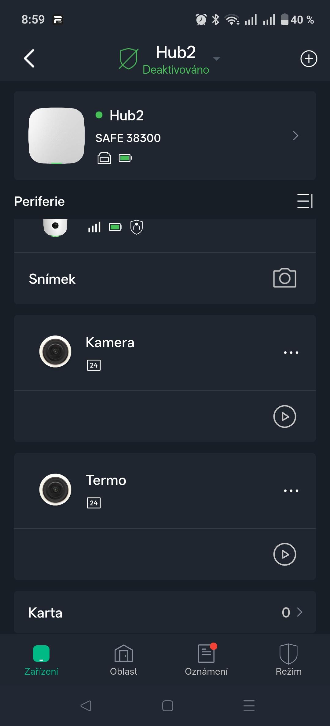
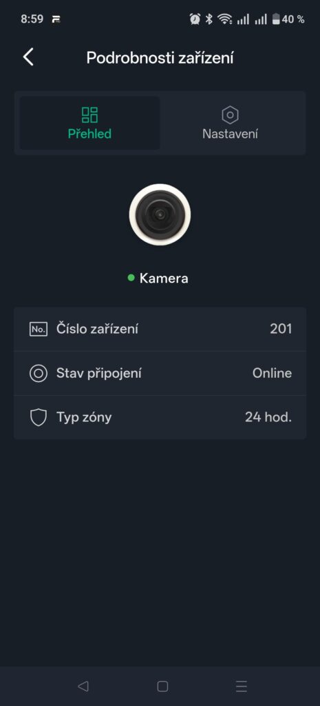
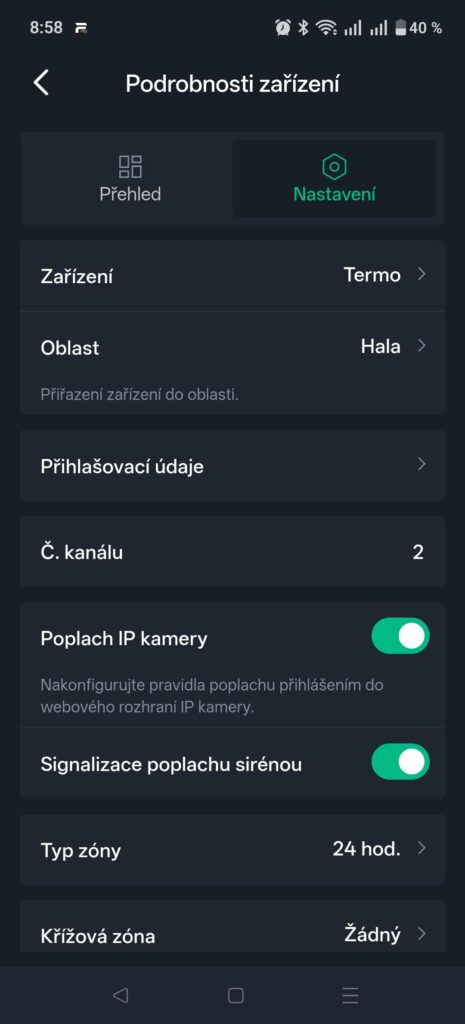
Step 3. Enable alarms from the camera into the ProSAFE system – in the HUB – Devices click the added camera – settings – switch on IP camera alarm, select the 24h zone type.
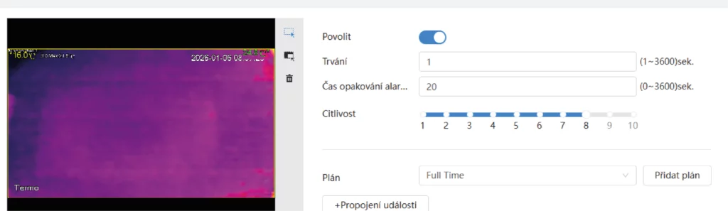
Step 4. In the camera web interface at its IP address, in the "Event", or "Event" menu enable fire detection in the Fire menu.
Warranty
The manufacturer warrants that the enclosed device will be free from any defects in material and workmanship under normal use and operation for a period of three years from the date of sale. The manufacturer's obligation under this warranty is limited to the repair or replacement of the device or any of its parts which it finds to be defective in material or workmanship, free of charge, after it has been sent together with proof of the date of purchase and with postage prepaid to the address of the service centre:
SAFE HOME europe s.r.o., Čechova 1005/4, 750 02 Přerov, Czech Republic.
This warranty becomes void if the product has been damaged, altered, misused, modified after purchase, or if it has ceased to function as a result of poor maintenance or improper placement.
Any implied warranties arising from this sale, including but not limited to implied warranties of description, merchantability and fitness for a particular purpose, are limited to the duration of this warranty.
Under no circumstances shall the manufacturer or any of its parent, affiliated companies, or our sales representative or distributor be liable for loss of functionality of this product, nor for any indirect, special, incidental or consequential damage, or for costs or expenses incurred by the consumer or any other user of this product, whether due to breach of contract, negligence, strict liability in tort, or for other reasons.
The manufacturer or any of its parent or subsidiary companies, or our sales representative or distributor, shall not be liable for any personal injury, property damage, or other special, indirect, incidental or consequential damage arising as a result of gas leakage, fire or explosion.
This warranty does not affect your statutory rights.